
The Aurea 5 Hybrid is a rebadged Chofu with a control box that, let’s say, has room for improvement. So i replaced its brain with an ESP32 running ESPHome — it talks straight to the outdoor unit and lets me set the flow temperature from Home Assistant.
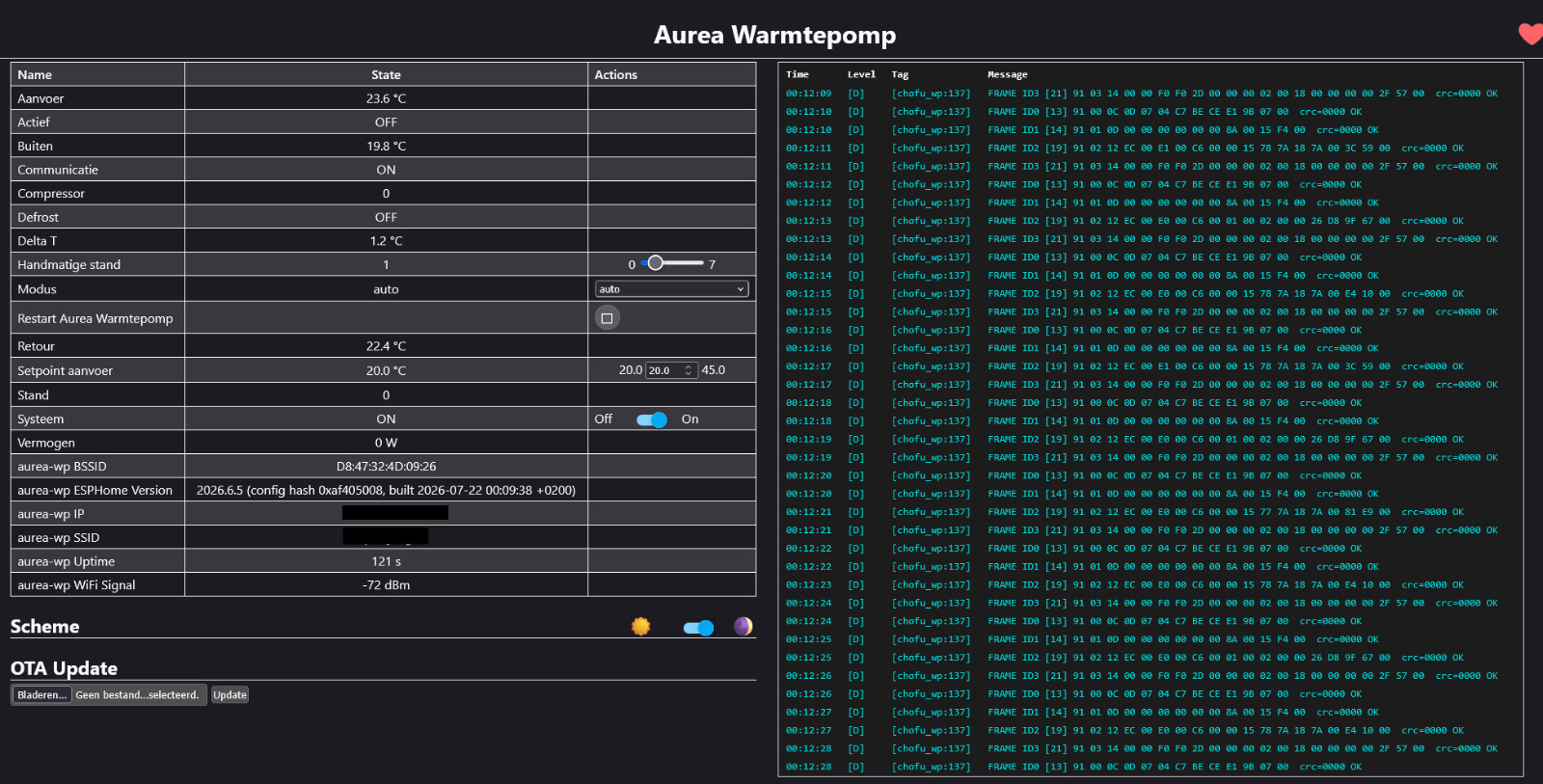
No Modbus, no OpenTherm to the outdoor unit — this cost-reduced Atlantic version talks its own protocol over two optocouplers. This is the one telegram that matters, the one that carries the actual command:
19 02 08 01 01 00 99 37
│  │  │  │  │  │  └──┴── checksum (CRC-CCITT)
│  │  │  │  │  └──────── (unused)
│  │  │  │  └─────────── power step (0-7)
│  │  │  └────────────── on / off
│  └──┴───────────────── message type + length
└────────────────────── header
Here’s the short version of how i got in.
Whose work this is built on
Let me be clear: i did not reverse-engineer this protocol myself. All the hard work was done by WackoH and _JGC_ in this Tweakers topic. WackoH put a logic analyzer on the line and mapped out the wiring and the telegrams; JGC turned that into a working ATmega2560 sketch. I also did not program a single line in this project, i’ve let Claude AI do this. Feel free to do what you want with it. I’ve instructed my AI to port their protocol work into an ESPHome component and put a simple controller on top of it — so i can drive the pump straight from Home Assistant instead of an Arduino with a screen.
The protocol in a nutshell
- 666 baud, 8N1 — the optocouplers are slow, so the whole thing runs at a crawl.
- The outdoor unit is the master; the control box answers.
- The control box sends four telegrams in a loop; only one carries the command (the one above).
- Every telegram is closed off with a CRC-16/CCITT checksum.
Cracking the checksum
This was the fun bit. AI had two known command telegrams that differed by exactly one byte:
19 02 08 01 02 00 → CC 64
19 02 08 01 01 00 → 99 37
So instead of guessing, AI brute-forced every common CRC-16 variant against both frames and looked for the one that produced the right two checksum bytes for each. Exactly one matched both: CRC-16/CCITT-FALSE (poly 0x1021, init 0xFFFF, big-endian).
Reading the pump back
The frames coming from the pump were trickier: they don’t end in a fixed marker, the next telegram just starts. But CRC-CCITT has a handy property — run it over a whole valid frame including its own checksum bytes and the result is 0. So AI logged every complete frame on the ESP and watched for that:
91 02 12 ED 00 E1 00 C6 00 ... crc=0000 OK
The moment crc=0000 lined up, the rest fell right out. The three temperatures sit at fixed offsets, little-endian, divided by ten: ED 00 = 0x00ED = 23.7°C supply, E1 00 = 22.5°C return, and so on. Power and compressor speed live in another frame.
The result
That’s the whole trick. The ESP now reads supply, return and outside temperature plus real power straight from the pump, and i set a target flow temperature in Home Assistant. The controller picks the power step itself and nudges it up or down slowly — so the compressor doesn’t slam to full power and wake the neighbours.
No level shifters, no fuss: the on-board optocouplers already isolate everything, so TX goes straight to the socket and RX comes back through a divider. Wiring and full code are in the repo.
THIS PROJECT IS AT YOUR OWN RISK. You’re poking around mains voltage inside the control box, and this is not endorsed by or affiliated with Atlantic or Chofu.
Credits again to WackoH and _JGC_ for the reverse-engineering. My code is on my GitHub.
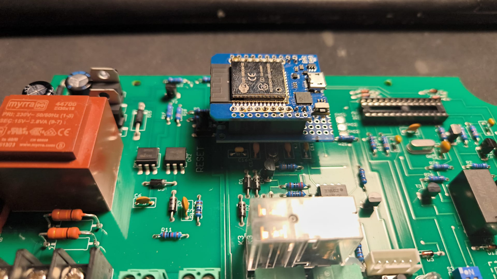
Howto connect this to the Atlantic unit?
                      CONTROLBOX-PRINT (bestaand)                    ADAPTER / ESP32
   ┌───────────────────────────────────────────────────────┐
   │  ZENDEN naar WP (niet-inverterend: pin26 HIGH = LED aan)│
   │                                                         │
   │   +5V ──►|── OK2 ── R10(330Ω) ──┐                       │
   │        LED-anode  LED-kathode   │                       │
   │                              collector                  │
   │                               [T2 BC547]                │
   │   pin26 ── R14(1k) ── base       │emitter               │
   │     ▲                            └── GND                 │
   │     └──────────────────────────────────────────────────┼──── GPIO17 (TX)
   │                                                         │
   │  ONTVANGEN van WP (emitter-follower, niet-inverterend)  │
   │                                                         │
   │   +5V ── OK1 collector                                  │
   │            OK1 emitter ──┬── R17(1k) ── GND             │
   │                          │                              │
   │                          └── R9(4k7) ── pin27 ──────────┼──┬─ GPIO16 (RX)
   │                                                         │  │
   │                                                         │ [10k]
   │                                                         │  │
   │                                                         │ GND
   │   pin7 ── +5V (LM7805)                                  │
   │   pin8 ── GND ──────────────────────────────────────────┼──── GND / 5V
   └───────────────────────────────────────────────────────┘
Be alert. the ESP32 draws more power than the LM7805 can deliver, so you should connect the ESP to a USB adapter lik the original plugwise thermostat was connected. But Do remember that you have to disconnect the pin7 on the socket. DO NOT connect two power supplies.
So if you feed the ESP32 via a usb power adapter, disconnect pin7.
If you connect the ESP32 with a USB Power adapter. You will only need a direct pin from GPIO17 to Pin26 of the socket, GPIO16 direct to Pin27 and a reisistor of 10k on GND to GPIO16. And ofcourse the ground connection Pin8 to GND of the ESP32.
Update: it can cool, too
Byte 4 of the command telegram sets the mode: 0x00 is off, 0x01 is heating. Someone on the forum mentioned that 0x02 might be cooling, but nobody had confirmed it and JGC’s sketch never used it. So i tried it.
It works. Within about six seconds the compressor kicked in, and the flow temperature dropped from 37.8°C to 23.8°C while the return sat at 30.0°C — so the water leaving the pump was 6.3°C colder than the water coming back. That’s not a sensor being weird, that’s the cycle genuinely running in reverse.
data2 = 19 02 08 <mode> <step> 00 <crc_hi> <crc_lo>
                   │
                   └── 0x00 = off, 0x01 = heating, 0x02 = cooling
Careful with this one: a central heating system usually isn’t insulated against cold water. Go below the dew point and your pipes and radiators will sweat. Keep the setpoint above ~17°C, or insulate first.
The bug that cost me an evening
Decoding the protocol turned out to be the easy part. Getting clean frames was the hard part.
Everything looked perfect while the pump was idle. But the moment the compressor started running, every long frame failed its checksum — while the short ones stayed fine. That pattern bugged me, because random electrical noise doesn’t politely skip the short messages.
The giveaway was in the raw log. My own telegram (19 01 0C ...) was showing up inside frames coming from the pump:
91 03 14 3B 53 9D 6E 15 00 22 1A 00 00 00 00 F2 93 00 19 01 0C
                                                        ^^^^^^^^
                                                        that's me talking
I was transmitting straight over the master. My send logic waited for the parser to report “frame finished” — but a corrupted frame meant that never happened, so it fell back to a blind timeout and just started sending anyway. One bad frame, and it snowballed.
The fix is to stop trusting the parser and watch the line instead: only transmit after at least 40 ms of silence. At 666 baud a single byte takes about 15 ms, so 40 ms of nothing means the pump is definitely finished. After that, all four message types came through clean, every single cycle.
If you ever try this yourself: seeing 0x19 bytes in the middle of a received frame is the tell. That’s your own transmission colliding with theirs.
Does the power reading actually match?
The pump reports a byte that maps to watts at 25.6 W per step. At 0x1A (26) that works out to 666 W, and the Shelly PM sitting in front of the unit measured 682 W at the same moment. About 2% off, which is close enough that i’ll take it.
How hot can it actually go?
Atlantic specs the Aurea at 55°C flow temperature, but that’s just the point where their hybrid setup hands over to the gas boiler — it’s not a limit of the hardware. The Chofu datasheet for the unit that’s actually in there says ~60°C for heating and 6.5°C~ for cooling. So i set the range to the full 6.5–60°C and let myself decide where to stop.
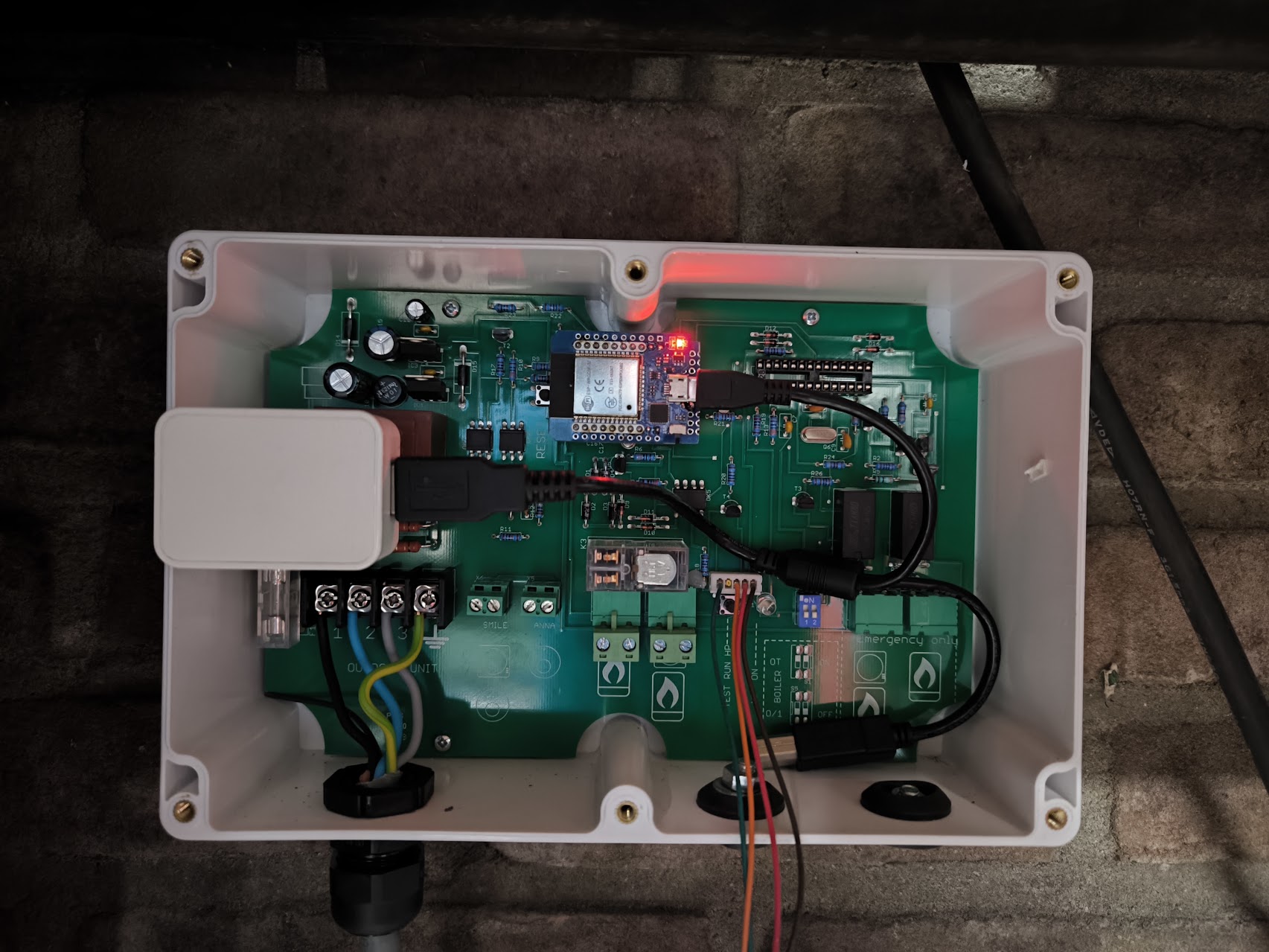
Next up:
Disconnect the second MCU, and get a DIYLESS slave board for the Anna thermostat. I’ve also generated via AI a ESPHome sketch to do this.